


Access Control
Boom Barriers
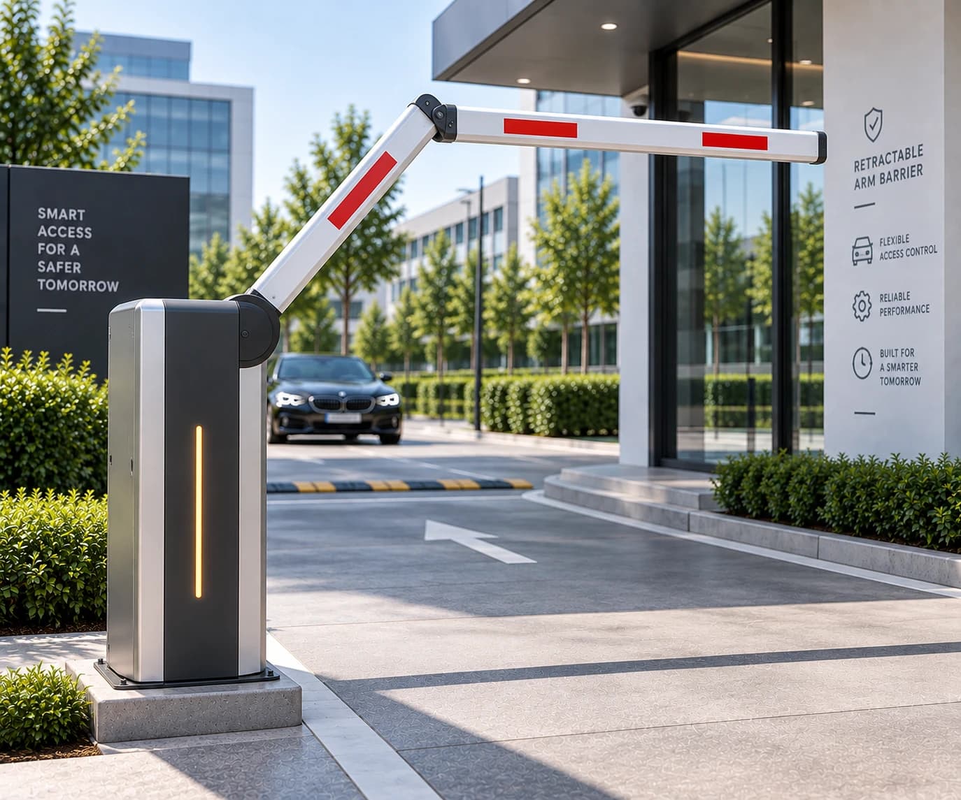
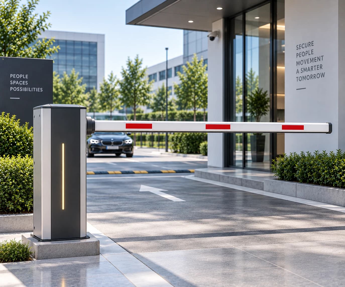
Automatic boom barriers for car park entries, plant gate houses and toll points, driven from loop detectors, readers, remotes or a gatehouse control.
3 configurations
Explore product
Access Control & Vehicle Barriers/Vehicle Access Control
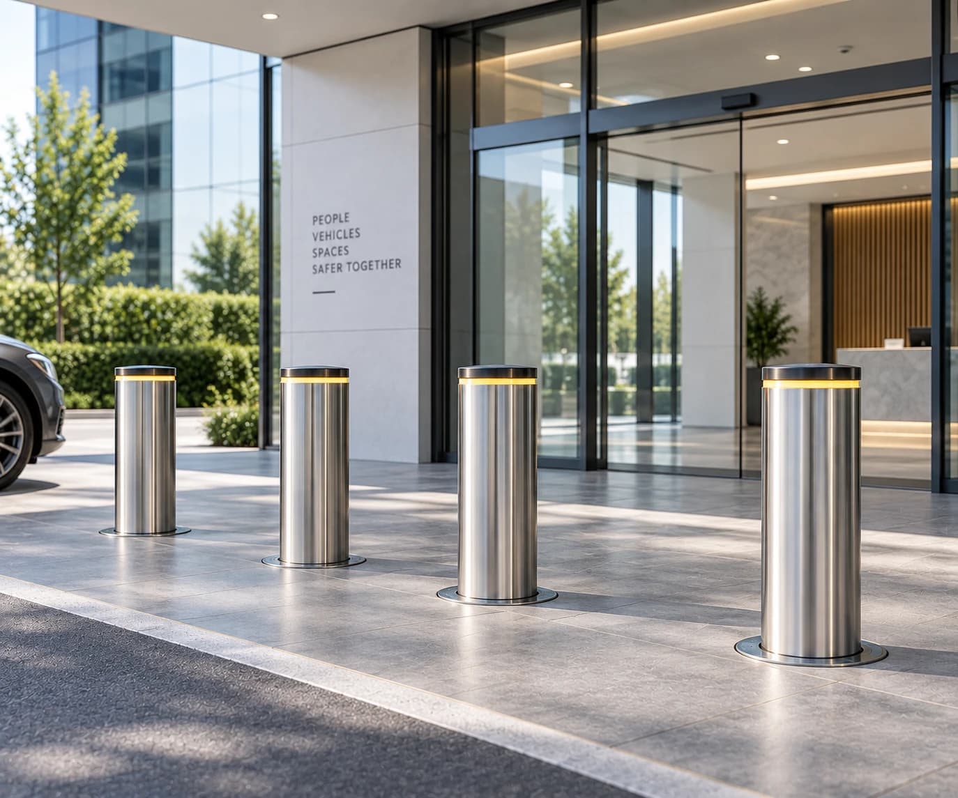
A vehicle line held physically, not advisorily.
 Access Control
Key specifications
* Final specification depends on door dimensions, configuration, operating environment and project requirements.
01Overview
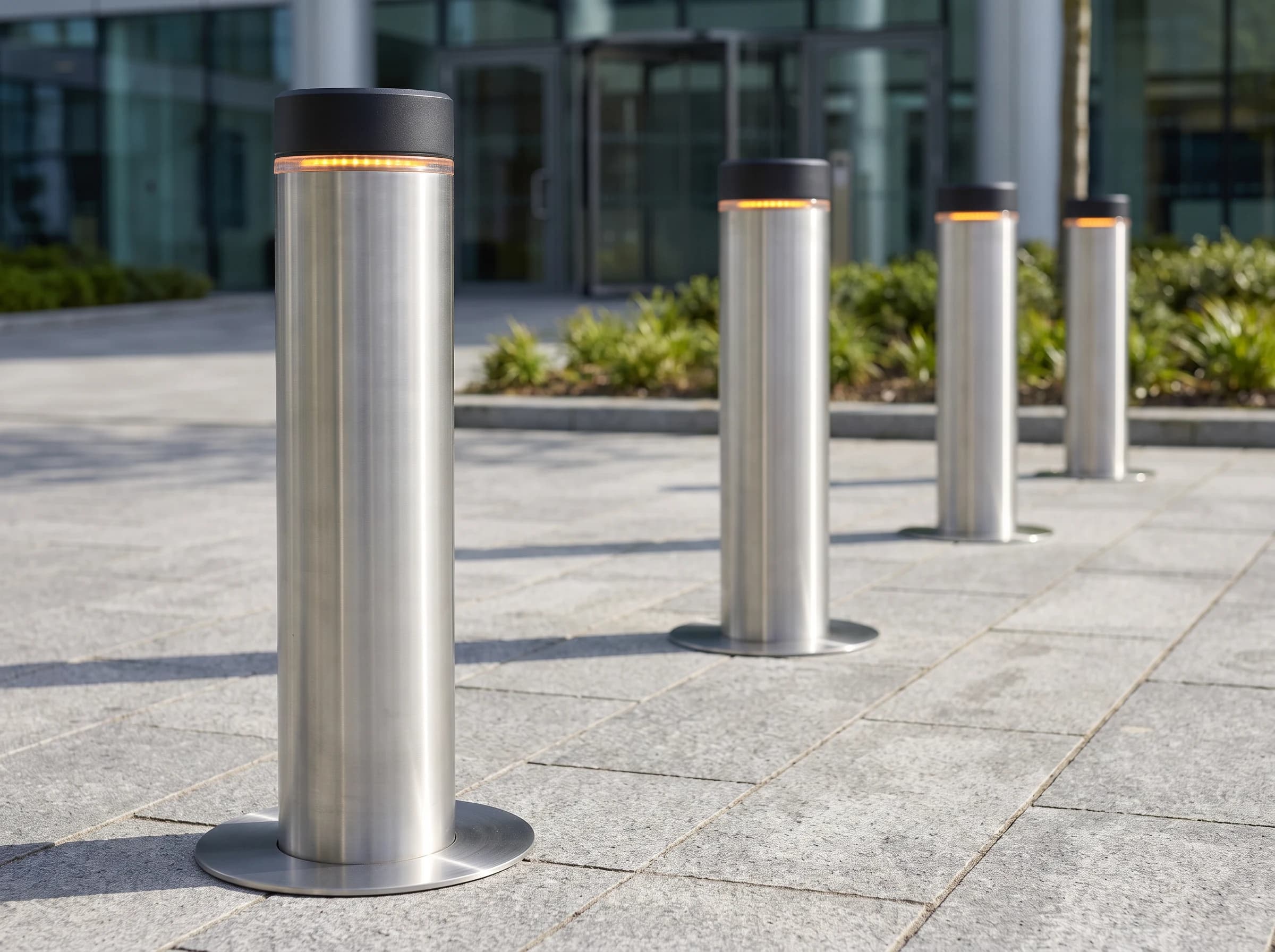
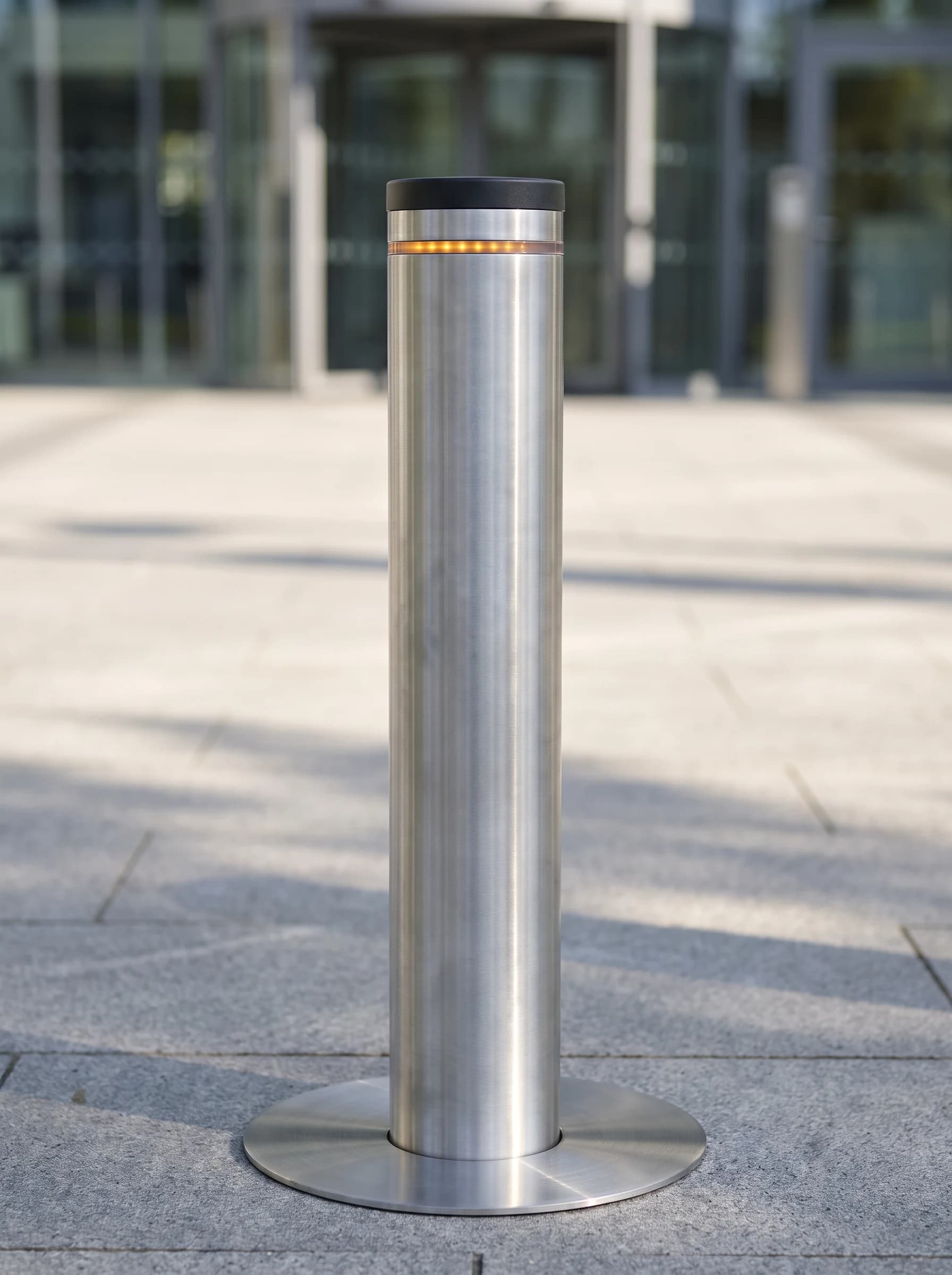
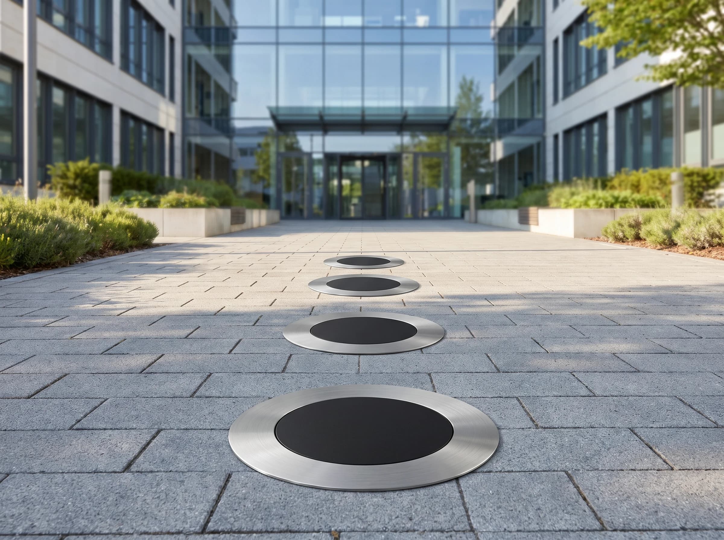
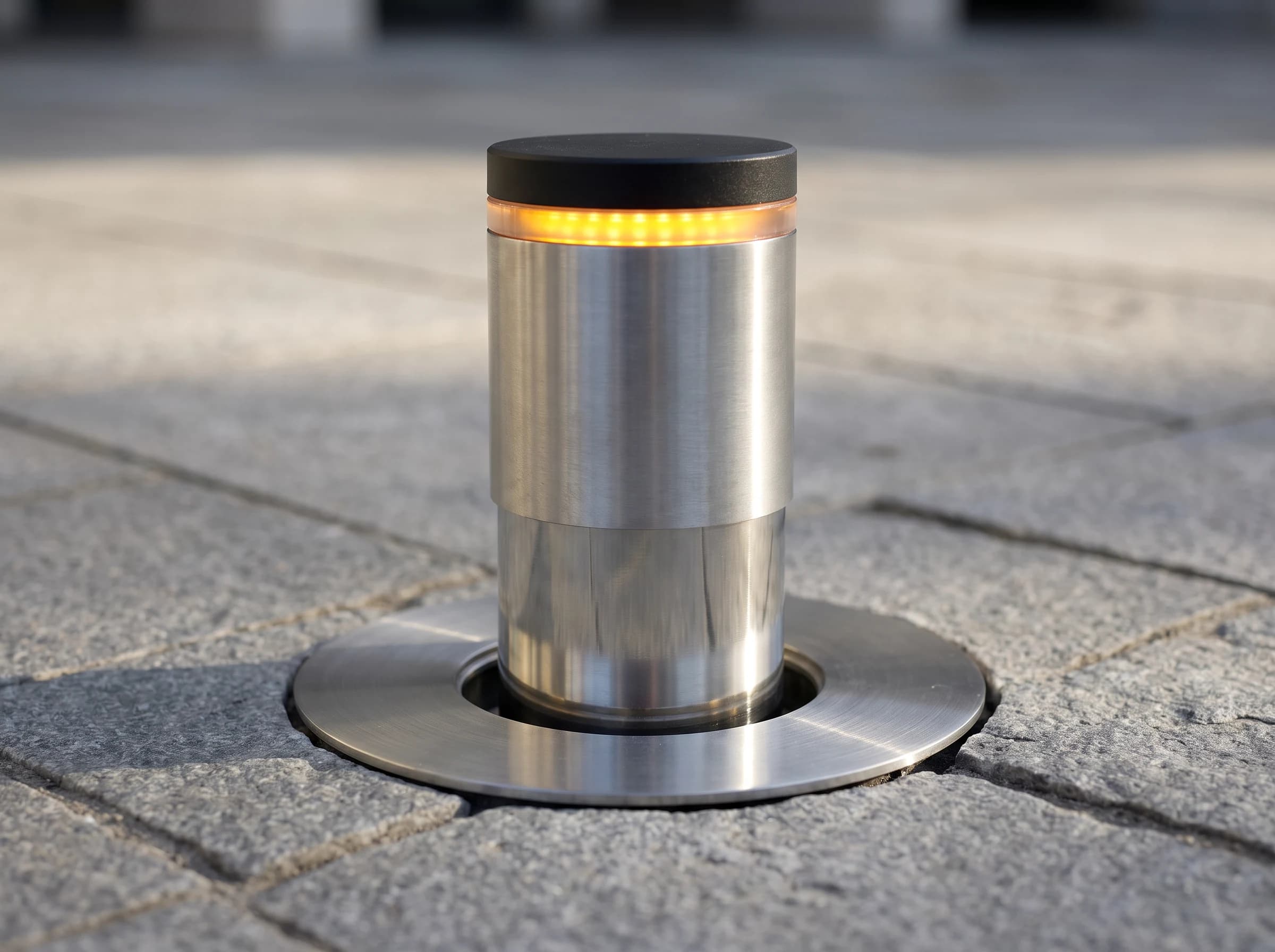
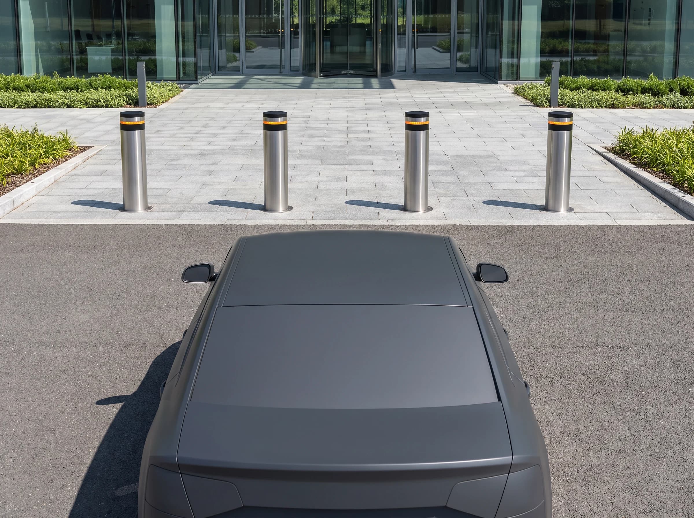
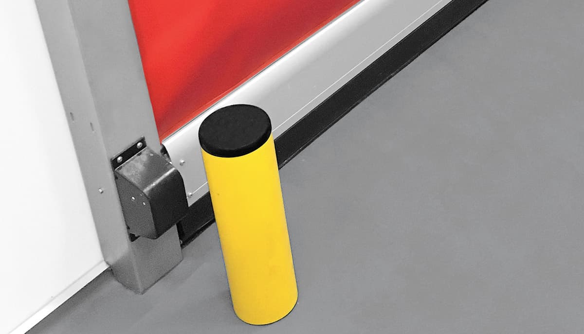
A bollard is the simplest way to make a boundary that vehicles physically cannot cross while pedestrians walk over it freely. Fixed units mark a permanent line; removable units open it occasionally for service access; automatic rising units retract into the road surface on demand and re-deploy behind the vehicle.
03Variants
The same product, built for a different job. Where a specification depends on opening dimensions, selected profile, operating duty or site conditions, the final configuration is confirmed during technical assessment.
A permanent line. The cheapest and most robust option where the line never has to open.
Lifted out with a key for occasional service access, then replaced. Suits lines that open a few times a month.
Retracts flush into the carriageway on demand and re-deploys behind the vehicle. For lines that open many times a day.
10Gallery
04Technical specifications
Technical data is shown first; features, applications, compatibility, installation, safety, ordering and downloads are a click away.
Only for products actually tested to an impact standard.
EN 12453 applies to powered vehicle barriers where they form part of a gate installation.
| Boom length or barrier width | Not applicable; the protected width is set by the number and spacing of bollards |
|---|---|
| Bollard diameter | Typically 200–275 mm depending on model |
| Bollard height above ground | Typically 500–800 mm depending on model |
| Foundation depth required | Typically around 1,000 mm including the foundation box; set by the supplied model's foundation drawing and site drainage |
| Cabinet or body dimensions | Drive housed in the bollard body or in a remote power-pack cabinet, depending on model |
| Opening time | Typically 5–9 s to rise, depending on model and height |
|---|---|
| Closing time | Typically 3.5–9 s to lower; rapid descent of about 1.2–1.5 s available on some hydraulic models |
| Mean cycles between failure | Not published as a cycle count; manufacturers rate models from semi-intensive to intensive use |
| Impact resistanceOnly for products actually tested to an impact standard. | Ranges from around 10 kJ on light-duty electromechanical models to over 100 kJ on hydraulic security models; crash-tested ratings apply only to the specific certified model |
| Body material and finish | Painted carbon steel with cataphoresis primer and polyester powder finish; AISI 316 stainless steel option |
|---|---|
| Boom or barrier material | Steel or stainless steel cylinder |
| Drive mechanism | Electromechanical or hydraulic, integrated in the bollard or in a remote power pack depending on model |
| Reflective marking and lighting | Reflective band and LED crown lighting; buzzer on some models |
| Supply voltage | 230 V AC single phase, depending on model |
|---|---|
| Power consumption | Around 300 W on electromechanical models; hydraulic models depend on the power pack |
| Battery backup | Optional on some models; most lower automatically on power failure so the lane is never blocked |
| IP rating | Typically IP67 for the buried unit, depending on model |
| Operating temperature | -20 °C to +60 °C typical |
| Activation devices | Push button, remote control, key switch, reader or gatehouse control through dry-contact inputs |
|---|---|
| Loop detectors | Loop detector inputs for safety and presence loops |
| Access system interface | Dry-contact inputs; traffic light and interlock outputs on the control unit |
| Manual release | Manual lowering by key; electromechanical models lower automatically on power failure |
| Photocells | Photocell input on the control unit |
|---|---|
| Ground loop safety | Safety loop holds the bollard down while a vehicle is over it |
| Behaviour on power failure | Lowers automatically on most models, leaving the lane open; hydraulic models lower by manual release |
| Product standardEN 12453 applies to powered vehicle barriers where they form part of a gate installation. | No single product standard governs rising bollards; crash-rated models are tested to PAS 68, IWA 14-1 or ASTM F2656 per model, and the supplied unit's own documentation applies |
|---|---|
| Conformity marking | As applicable to the supplied unit and market |
| Certificate reference | Crash-test or manufacturer's documentation for the supplied model; available on request |
Final specification depends on door dimensions, configuration, operating environment and project requirements.
FAQ
Engineering enquiry
Five answers about the opening are usually enough for us to come back with a configuration and a price.

Get in touch
If it is easier to describe the opening than to write it down, call or message us and we will work through it with you.